Application of Automatic Cable Tie Cutting Machine on Nail Fixture Plate
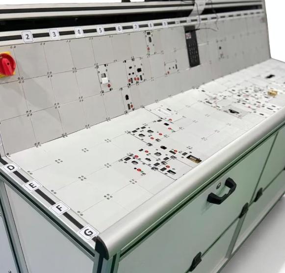
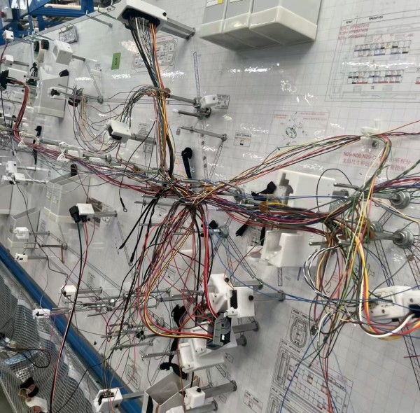
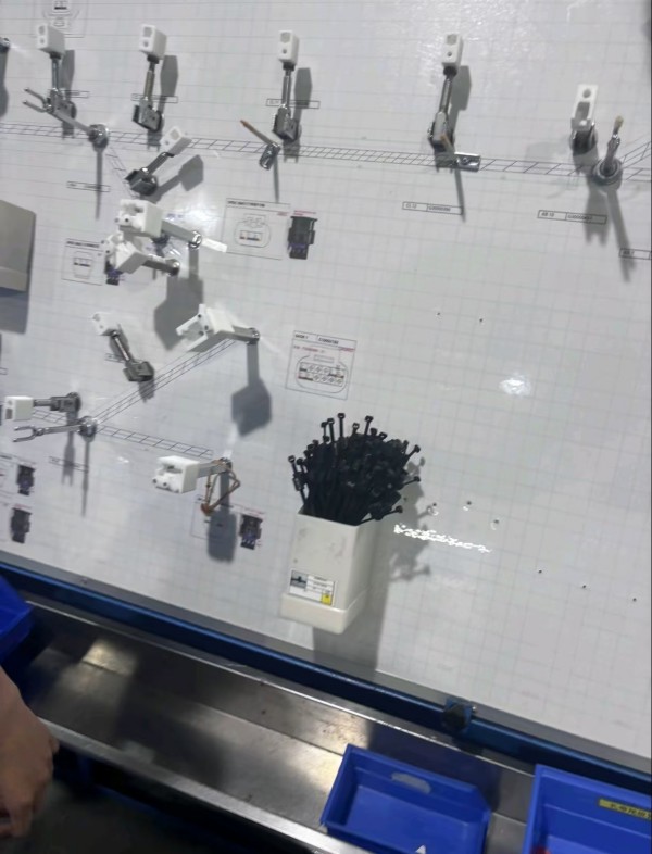
I. Background: Wire Harness Bundling is a High-Frequency, Yet Easily Overlooked Process In automotive/electronic wire harness production, cable tie bundling is one of the most frequent actions. A moderately complex wire harness often requires a dozen or even dozens of cable tie fixing points. The traditional method is: the operator arranges the wires with one hand and manually threads the cable ties with the other, then uses diagonal pliers or a manual cable tie gun to tighten and cut off the excess material. From the workstation diagram of the nail fixture plate you provided, we can see a typical work site: a large number of metal quick clamps, adjustable positioning arms, and track grooves are arranged on the white grid plate surface for fixing wires and nails according to the drawing; the plate surface is affixed with work instruction labels and diagrams; black cable ties are neatly inserted in the white box next to it, and the blue workbench below is equipped with a slide and storage box. This fixture solves the problem of "correct placement," but "good bundling" still highly depends on human feel.
II. Four Major Pain Points of Manual Cable Ties Inconsistent Tightness:
The tightening force varies significantly between the same person at different times and between different people. Too loose a fit can cause the harness to loosen and the clips to shift under tension; too tight a fit can damage the insulation layer and even cause stress whitening and cracking at the base of the clips (such as CLIP-BY-151 clips). Uncontrolled excess length: Manual cutting results in inconsistent lengths; too long requires secondary trimming, too short risks disengagement, and the cut may leave burrs that could scratch the operator or adjacent wires. Efficiency bottleneck: The three actions of threading, tightening, and cutting are sequential, with time spent on each piece concentrated on "finding the angle and aligning the hole," creating a hidden black hole in standard work time. Occupational health: Prolonged repetitive gripping movements can easily lead to finger and wrist strain.
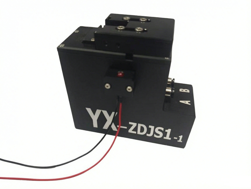
III. Working Logic of Automatic Cable Tie Cutting Machine The automatic cable tie cutting machine (automatic cable tie gun/cable tie machine) integrates the four actions of "cable feeding—threading—tensioning—cutting" into a single trigger: Automatic cable feeding: The nozzle continuously supplies cable ties, eliminating the need for manual cable picking and threading; Tension preset: The tension is preset according to the wire diameter and rivet specifications (usually adjustable in multiple levels, some models have digital display), executed by a mechanical/pneumatic mechanism, unaffected by the operator's grip strength; Automatic cutting: After tensioning to the correct position, the cutter cuts close to the surface, with residual material controlled within 1 mm, resulting in a clean, burr-free cut; Residual material collection: Some models include residual material collection to prevent broken cable ties from falling into the wire harness or tooling fixtures.
IV. Application Scheme Combined with Nail Fixture Plate
1. Workstation Layout The automatic cable tie cutting machine is suspended by a balancer or fixed to the top/side of the nail fixture plate using a bracket. The weight of the gun body is borne by the balancer, and the operator only needs to lightly grip the guide. 1. The workstation maintains a single-handed cycle of "left hand organizing the cable, right hand operating the cable gun," with the other hand always used to press the cable harness into the positioning slot of the clip.
2. Parametric operation: In addition to the original cable tie specifications and binding point positions, two key parameters are added to the work instruction label on the tooling plate: tension level and excess material length requirement. In this way, the tooling plate is upgraded from a "positioning tool" to a "parameter carrier," allowing even newcomers to do it correctly on the first try.
3. Clip protection is the core: The greatest value of an automatic cable tie machine lies not in speed, but in controllable tension. For clip-type fixing points, the upper limit of tension needs to be set according to the clip material (commonly PA66, POM) and clip foot structure—enough to tighten the cable harness without subjecting the clip root to interference stress. This is almost impossible to guarantee manually.
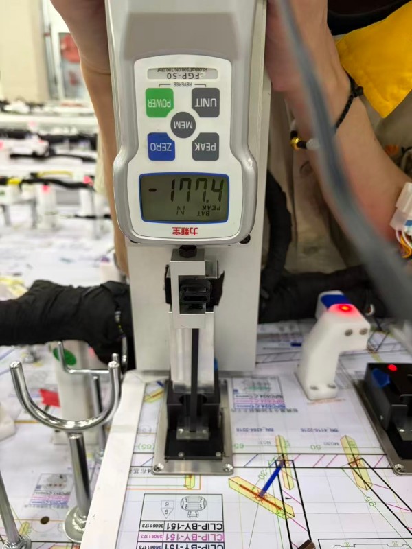
4. Closed-loop tension testing: The second picture you provided is the verification end of this closed loop: a pull-out test is performed on the assembled cable tie/clip combination using a digital display tension gauge. The reading in PEAK mode in the picture is -17.04 N. The correct way to use this type of data is as follows: Capture the maximum value at the moment of pull-out in PEAK mode as a measured value of the "holding force" of that cable tie point; Set a lower limit according to customer drawings or internal specifications (e.g., requiring the holding force of a certain type of clip fixing point to be no less than a certain value), and use the measured value to perform process capability analysis; After each change of cable tie batch, clip mold, or adjustment of cable tie machine tension setting, resample and test to form a correspondence table of "equipment parameters - measured tensile force", and then calibrate the tension setting in reverse.
Prev:What is the important role of wire harness continuity testing in automotive OEMs