I. Technical Specifications
1. Power supply and power consumption
o Voltage range: 12-24V DC ±10% (Ripple P-P value ≤10%)
o Power consumption: Maximum 300mW Maximum voltage: 24V (standard mode)
o Caution : Use of AC power is strictly prohibited, as it may cause an explosion or fire.?
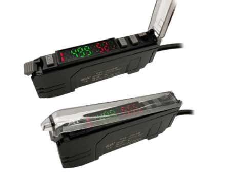
2. Detection Characteristics (Example of YH-303RGB NPN model and YH-303PRGB PNP model)
o Light source : RGB 3-color LED, 4 element light-emitting two.
o Display Indicators: Operation Indicator: Red LED, Dual Digit Monitor: Dual 7-digit display, threshold value (4-digit green LED indicator) and current value (4-digit red LED indicator) are lit together. Current value range: 0-9999.
o Power supply: Between 12 and 24VDC ±10%, Ratio (P-P): 10% maximum Class 2.
o Detection method : Light intensity detection MARK and color auto-matching detection C.
o Response time : 33US in CONTRAST mode, 80US in CLOLOR mode.
o Ambient temperature: -10 to +55℃ without freezing.
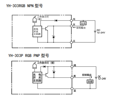
3. Output Circuit:
II. Operation Panel and Functions
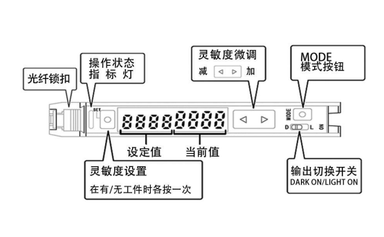
Basic Function Operation.
1. Power-on display 960 999 Short press UP DOWN key to adjust the size of setting value directly.
2. Press and hold the MODE key for more than 3 seconds to enter the following process: STND 1999 STND flashes:
Short press  to jump from SHS,HS,STND ,ULTRA,GIGA. SHS has the fastest response speed, but has poorer color recognition ability. GIGA has the slowest response speed, but has the strongest color recognition ability.
Short press MODE button to enter: CONT 1999 CONT blinking.
Short press to adjust CONTRAST and COLOR function mode.
CONTRAST is the common color-coded detection mode, the amplifier will select one of the RGB receiving elements, COLOR mode is the common color-matching detection mode, 1000ths of a thousand means that the colors are exactly the same, it is generally considered that 900ths of a thousand means that one color is used. 1000ths of a thousand means that the colors are exactly the same. In COLOR mode, the object shaking in front of the fiber can be detected normally, and half of the shaking of plus or minus 4MM can be used normally.
III. Working mode settings
1. Setting sensitivity
Two-point calibration in CONTRAST mode.
Step 1, a measured workpiece placed in front of the optical fiber, press the SET (Set) button (press the button time not more than 2 seconds).
Step 2, without placing any work piece or background object in front of the fiber optic head, press the SET button (press the button for no more than 2 seconds).
2. Initial Setup
In display mode 86 999 press MODE at the same time, press the SET button for at least 3 seconds, the screen displays: Init. to complete the initialization: detection mode for COLOR, T-2P, TOFF mode, the color threshold value is 900.
3. Use tips: when the return light is very weak, it will display NNNN, very strong, it displays VVVV. At this time, adjust the distance from the optical fiber to the detected object.
IV. Installation and wiring
Installation on DIN rail
1.Align the slot on the bottom of the main unit with the rail. Push the main unit in the direction of arrow 1 while tilting it in the direction of arrow 2.
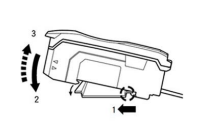
2. To remove the sensor, lift the main unit in the direction of arrow 3 while pushing the main unit in the direction of arrow 1.
Mounting to the wall (only for the main module)
Place the modules on the optional mounting bracket, mount them together and secure them with two M3 screws.

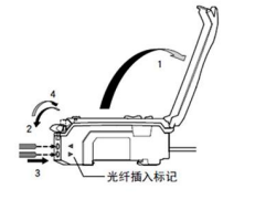
Connecting the Fiber Optic Module
1. Open the dust cover in the direction of arrow 1.
2. Move the fiber optic locking lever down in the direction shown by arrow 2.
3. Insert the length marked on the fiber optic module mark into the fiber optic hole.
4. Move the fiber lock lever down in the direction shown by arrow 4.
5. If you are using a thin fiber optic module, you will need to use the supplied adapter.
6. If the correct adapter is not connected, the thin fiber optic module will not detect the target correctly. (Adapters are provided with the fiber optic module at.)
7. If connecting a coaxial reflective fiber optic module to an amplifier, connect a single fiber to the transmitter side and a multi-fiber to the receiver side.

V. Safety Precautions
To ensure your safety, please be sure to observe the following regulations when using:
1. This product is for target detection only. Do not use this product for the purpose of protecting the human body or parts of the human body.
2. This product should not be used as an explosion-proof product. Do not use this product in a hazardous location and/or in a potentially explosive atmosphere.
3. This product is a DC power supply type sensor. Do not use AC power. Failure to do so may cause the product to explode or catch fire.
4. Do not wire the amplifier along power or high voltage lines, as the sensor may malfunction or be damaged due to noise.
5. When using a commercial switching regulator, be sure to ground the frame ground terminal and the grounding terminal.
6. Do not use the unit outdoors or in a location where external light can directly enter the light receiving surface.
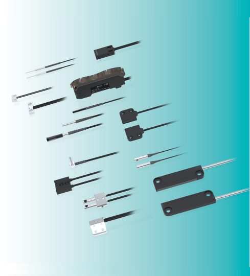
VI. Combining Fiber Optic Sensors with Fiber Optic Sensor Heads
There are over 100 specifications and models of fiber optic sensor heads available. Based on the customer's specific application and environment, the optimal choice is provided. These heads are compatible with fiber optic amplifiers to achieve extremely high reliability and extremely simple operation. Follow the steps below:
Selection Guidelines
Physical Property Compatibility: Consider the type of physical quantity being measured (e.g., temperature, pressure, displacement, etc.), measurement accuracy requirements, and installation environment. For example, if used in high-temperature environments, heat-resistant fiber optic sensors should be selected.
Interface Compatibility: Match the sensor interface type (e.g., USB, RS232, etc.) with the corresponding data acquisition device or signal processor.
Installation and Connection
Positioning Installation: Ensure that the fiber optic sensor is in full contact with or close to the physical quantity being measured, and consider the characteristics of the physical quantity distribution and installation feasibility.
Signal Transmission: Transmit the optical signal to the data acquisition device via the fiber optic cable, ensuring a secure and reliable connection.
Parameter Settings and Calibration
Configuration Parameters: Set parameters such as sampling frequency and sensitivity according to the sensor's characteristics.
Calibration Verification: Calibrate the sensor's output signal using a standard reference source to ensure accurate correspondence with the actual physical quantity.
Testing and Maintenance
After completing the settings, observe the signal stability. If abnormalities occur, inspect the connections or recalibrate the sensor.
Tag:
Prev:Cylinder Application Industry-Industrial Automation
Next:Understand the production process of wiring harness and the related processes


 to jump from SHS,HS,STND ,ULTRA,GIGA. SHS has the fastest response speed, but has poorer color recognition ability. GIGA has the slowest response speed, but has the strongest color recognition ability.
 to adjust CONTRAST and COLOR function mode.


